DISCLAIMER

All rights of photos and text reserved. Usage of photos or text from my blog on other websites or for any other purpose only with prior permission. If you want to use any material from my blog please contact me by email.

Monday, June 30, 2014

Tube of the Month : The 25AX4

Hi!

Last months tube was a rather large and fairly old transmitting type rectifier. This month we are moving to the other end. A much more modern diode designed for consumer applications. The 25AX4.


Readers of my blog know that I am very fond of TV Damper Tubes and use them almost exclusively as rectifiers in my power supplies. My favourite among them is the 6AX4.

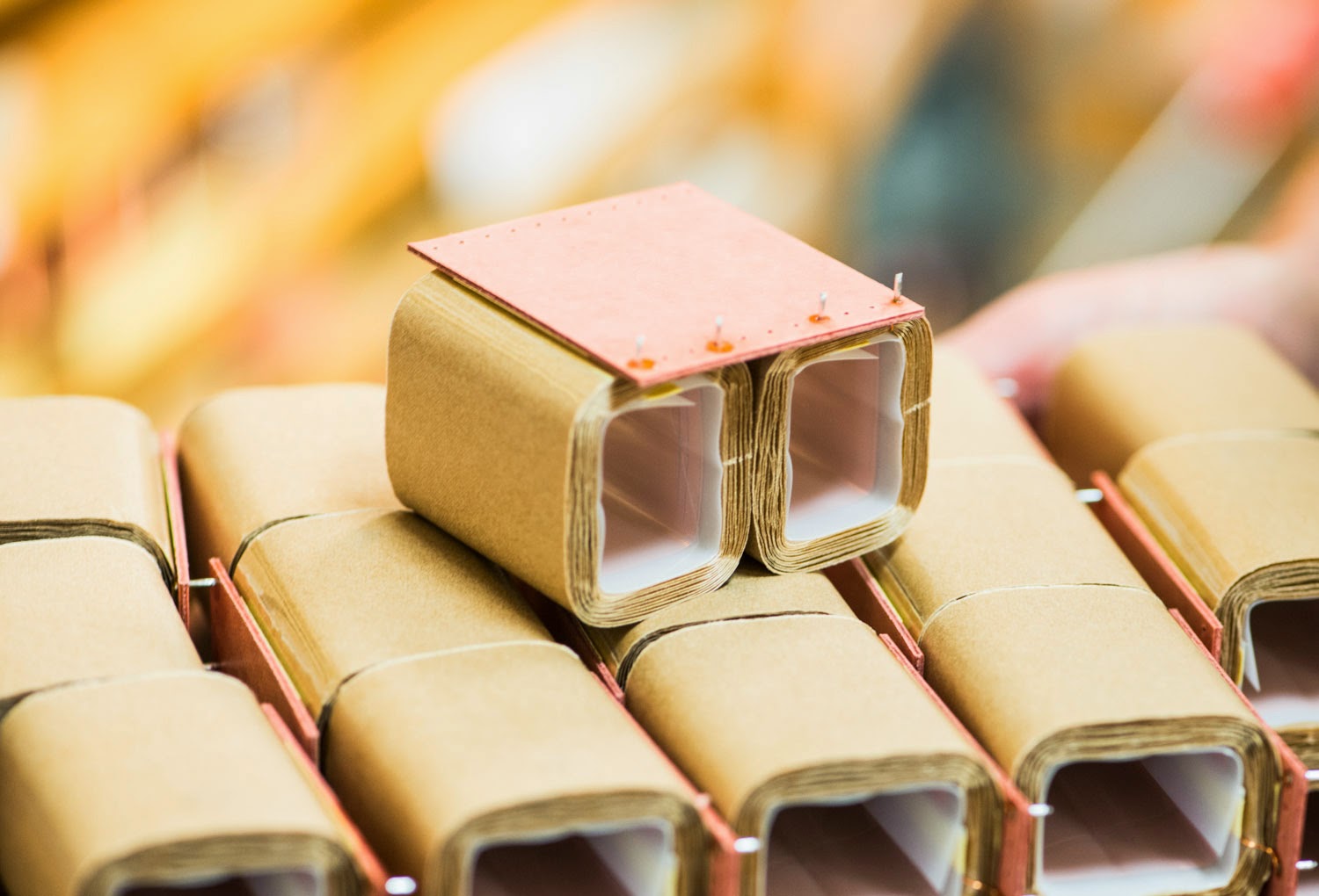
The 25AX4 belongs to the same family. It only has a different heater which needs 25V instead of the 6.3V of the 6AX4. The current needed to light it up is a modest 300ma. All other parameters are the same as those of the 6AX4. It also has the same octal base and pinout which is shown on the left. What makes this particular version of this tube family interesting is the heater voltage requirement. It could be heated from a 24V transformer. This is still well within he limits for the tube to work well and 24V transformers are available cheaply. So if you are on a severely limited budget and $2-$3, which is the typical price of the 6AX4, is still too high, pick up some 25AX4 which can be found at even lover prices. Especially if purchased in bulk packs like this:


Each of the boxes contains 100 tubes, nicely packed in carton trays.


Like others this tube was build in various styles:


Three different versions with a regular base and one with a shorter one, also called coin base.

A closer look at the coin base tube:


Two 25AX4GT in front of a 'wall' of Sylvania boxes:


Since the only difference between the 25AX4 and the 6AX4 is the heater voltage and current, we would expect their construction to be quite similar except for the heater wire. Here is one of each from the same manufacturer and of the same coin base construction style.


No apparent difference between the 25AX4 (top) and 6AX4 (bottom).


The plate structures look identical.


In this case the only difference is the printing of the tube type on top of the 25AX5 while the other has none.


Opening them:


The difference becomes apparent, when the heater is pulled out of the cathode sleeve:


The 25AX4 (top) has a much longer heater wire which is folded several times to fit in.

Removing the heater completely, 25AX4:


6AX4:


Close ups:


Removing the heater wire from the isolation spiral. The 25AX4 heater is substantially longer allowing the large voltage across it:


The heater wire of the 25AX4 has 16 folds, while the 6AX4 has 4, so 4 times the length, which results in 4 times the resistance, and is equal to the 4 times difference in heater voltage.

The cathodes are identical, as expected:


A 25AXGT with the heater lit up:


A great tube, cheaply available and the warehouses of tube dealers are still full of them.


Best regards

Thomas


Thursday, June 26, 2014

Differential 10Y Line Preamp, Part 1

Hi!

I am often asked when I will finally present a push pull amplifier. In fact I am often perceived as being prejudiced pro Single Ended. While I do like the sound of my single ended designs, I am by no means religiously bound to this concept. In fact I did build push pull amplifiers in the past and probably will do so in the future. At the latest when somebody orders a push pull amplifier from me.

Such has happened for a preamplifier. A user of my 10Y line stage asked me for possibilities to upgrade it. So I proposed a differential version of it.


Differential in this case means that it will be a self balancing circuit. The beauty of such a concept is the possibility to build it without any capacitor in the signal path. And that's how this line stage will be done. Lot's of iron, no capacitors in the signal section. Everything decoupled from the power supply. Of course that means that 2 10Y tubes will be needed per channel. 4 of them in total. This is the top metal plate of the signal section:


The left half will be occupied by filament chokes. For the 4 sockets to fit, I had to use some different ones as usual, which have a smaller footprint. These allow the vibration damped sub assemblies to be narrower.

I often get emails about my technique of vibration damped sub assemblies for the tube sockets. So I will show this a bit more in detail in this first part. These are the basic elements used for that:


A rubber cylinder with metal threads at both ends. Threaded metal blocks get attached at either end.

The small metal plates which carry the tube sockets have threaded holes on the bottom:


Tube socket mounted:


Then the metal blocks get attached to the plate with screws:


The rubber elements screw into the sides of these metal blocks:


The small wire is there to make an electrical connection from the sub plate to the main plate. Another set of the metal blocks goes onto the other side of the rubber pieces:


The outer metal blocks get attached to the main metal plate:


View from the other side:


Stay tuned for updates on the construction of this preamp.

Best regards

Thomas

Saturday, June 14, 2014

Lundahl Transformers of Sweden : The Visit

Hi!

After using Lundahl transformers and chokes for about twenty years, it was about time to visit their factory.


Lundahl Transformers AB was founded 1958 by Per Lundahl's parents Gunnel and Lars. After running the operations in the basement of their house in Stockholm for a few years, they moved to Norrtälje and opened the factory there. Norrtälje is a beautiful city about 70km north of Stockholm.


Situated at the coast, Norrtälje has direct access to the baltic sea:


Houses are built in the typical swedish style:


The Lundahl factory is in Tibeliusgatan.


The factory is also built in the typical swedish fashion, blending in nicely with the town:


Inside everything is meticulously organised. Manufacturing is following well thought out processes which ensure the high consistency which Lundahl is famous for.

The floor with winding machinery:


All the machines are developed, built, programmed and maintained in house!


6 coils are wound at once. See the machine in action in this short video:


Most of the delicate work of winding and assembly is carried out by women.


pre wound coils, ready for the next assembly step:


A trademark of Lundahl is the dual coil construction. Each transformer is made of two identical coils:


Adding the core:


In this case stacked laminations. 

The assembled transformer, ready to be put into the housing:


After the wire is soldered to the pins, the assembly is housed in the mu metal cans and labelled:


Lundahl doesn't like to leave things up to chance, hence as much as possible is done in house. While other manufacturers would source housings, Lundahl makes them, again using own machinery:


A spool feeds a strip of mu metal into the machine which bends it into the shape without destroying the permeability.


A typical example of the details which are taken care of is this rig with a bottle of alcohol which cleans the surface before the metal is bent and welded into shape:


The terminal pins are another example of the impressive in house capabilities.


What seems like a rather mundane item is not sourced from outside but made to Lundahls own quality standards:


This machine cuts pieces from metal strips fed by spools and shapes them into hollow pins which take the copper wire from the transformers coils.


Chokes, interstage and output transformers are wound on the well known C cores. Lundahl receives the high flux grain oriented metal for the c cores in such large drums:


This is then cut into the widths for the different transformer types:


Wet polishing after cutting:


Cores are wound from this strip.


Wound cores:


Then the cores are cut to obtain two separate 'C' shaped parts:


The corners are carefully chamfered and the surface is meticulously polished to obtain a consistent and precise air gap.

Coils and cores for C-core transformers and chokes are stored and assembled just before an order is shipped.


A coil for output transformers:


Pre assembled choke coils, with paper insulation:


The gap is defined at final assembly by the use of foil with appropriate thickness:


This way single ended transformers can be made with custom air gaps for a wide range of currents.

Small transformers in mu-metal housing are stocked in good quantities for the most commonly ordered types:


With nothing left to chance during each production step, of course there are detailed quality checks done on every single transformer or choke.


A whole set of measurements is done on each part, for example distortion and inductance tests.


Parts ready for shipment:


The photos above only show a part of the facilities. Here are a few others. For example the room for vacuum impregnation:


The annealing furnace:


Part of the wire stock:


For maintaining all the machinery and to build new ones if required, there is a fully equipped metal shop:


It has been a great experience to get a real life impression of the extremely structured work flow and the atmosphere of the highly concentrated and motivated people who make these products. I'd like to thank the staff of Lundahl Transformers for the great day. And especially thanks to Per Lundahl for the hospitality.


Keep on the great work!


Best regards

Thomas